Signalhead (talk | contribs) |
Signalhead (talk | contribs) →External links: Transferred a link from Railway signal article |
||
| Line 61: | Line 61: | ||
==External links== |
==External links== |
||
* [http://www.signalbox.org/ John Hinson's site 'The Signal Box'] |
* [http://www.signalbox.org/ John Hinson's site 'The Signal Box'] |
||
* [http://www.studio433.co.uk/exeterwest/ Exeter West Signal Box] |
|||
* [http://railwayscenes.fotopic.net/c871158.html Over 100 photographs of traditional mechanical signal boxes on Britain's rail network] |
* [http://railwayscenes.fotopic.net/c871158.html Over 100 photographs of traditional mechanical signal boxes on Britain's rail network] |
||
* [http://www.simsig.co.uk Free simulations of several British IECC signal boxes] |
* [http://www.simsig.co.uk Free simulations of several British IECC signal boxes] |
||
Revision as of 21:45, 11 May 2007
A signal box or signal cabin is a building from which railway signals and points are controlled. In North America, the somewhat equivalent term interlocking tower is used.

History
Originally, all signalling was done by mechanical means. Points and signals were operated locally from individual levers or handles, meaning that the signalman had to walk between the various pieces of equipment to set them in the required position for each train that passed. Before long, it was realised that control should be concentrated into one building, which came to be known as a signal box.
Control apparatus
Lever frame
The earliest signal boxes housed mechanical lever frames. The frame was usually mounted on a beam beneath the operating floor. Interlocking was attached to the levers, which ensured that signals showed the correct indication with regard to the points and were operated in the right order. Wires or rods, connected at one end to the signals and points and at the other to levers in the signal box, ran alongside the railway.
Levers are painted according to their function, e.g. red for stop signals and black for points, and are usually numbered, from left to right, for identification. In most cases, a diagram of the track and signalling layout is mounted above the lever frame, showing the relevant lever numbers adjacent to the signals and points.
Power frames have miniature levers and control the signals and points electrically. In some cases, the interlocking was still done mechanically, but in others, electric lever locks were used.
In a few cases, signals and points were operated pneumatically upon operation of the appropriate lever or slide.
Control panel
In a signal box with a control panel, the levers are replaced by buttons or switches, usually appropriately positioned directly onto the track diagram. These buttons or switches are interfaced with an electrical or electronic interlocking. In the UK, control panels are of the following types:
- Individual Function Switch (IFS)
- A separate button/switch is provided for each signal and for each set of points. This type of panel is operated in a similar manner to a lever frame. The signalman must move each set of points to the desired position before operating the switch or button of the signal reading over them.
- This type of panel needs the least complex circuitry but is not suited to controlling large or busy areas.
- One Control Switch (OCS)
- A separate switch/button is provided for every signalled route. There will be as many switches/buttons per signal as there are routes (i.e. signalled destinations) from that signal. To set the desired route, the relevant switch or button is operated. All points within the route are automatically set to the required position.
- Individual points switches are provided, but they are normally left in the central position, which allows the points to be automatically set by the action of setting a route.
- Entrance-Exit (NX)
- This type of panel has one switch/button provided for every signalled route (except that some panels have separate 'entrance' and 'exit' devices). To set a route, the signalman operates the device for the 'entrance' signal, followed by the device for the 'exit' (destination) signal. All points within the route are automatically set to the required position.
- Individual points switches are provided, but they are normally left in the central position, which allows the points to be automatically set by the action of setting a route.
Similar principles of operation as described above are applicable throughout the world.
Visual Display Unit
Modern signal boxes nowadays tend to be provided with VDU based, or similar, control systems. These systems are less expensive to build and easier to alter than a traditional panel. In the UK, large modern signal boxes are typically of the Integrated Electronic Control Centre type. Variations of these control systems are used throughout the world.
Present day
Nowadays, some old-style signal boxes can still be found. Some still control mechanical points and signals, although in many cases, the lever frame has been removed or is out of use, and a control panel has been installed. Most modern countries have little, if any, mechanical signalling remaining on the rail system. Both in the UK and Ireland, however, mechanical signalling is still surprisingly common away from the busiest lines.
The modern control centre has largely replaced widespread signal cabins. These centres, usually located near main railway stations, control the track network using electrical or electronic systems. One such system is CTC, Centralised Traffic Control.
References
- Kichenside, G. and Williams, A., (1998), Two Centuries of Railway Signalling, Oxford Publishing Co., ISBN 0-86093-541-8
- Vanns, M.A., (1995), Signalling in the Age of Steam, Ian Allan, ISBN 0-71102-350-6
See also
- Area Signalling Centre
- Lever frame
- Interlocking
- Route relay interlocking
- Ground frame
- Railway signalling
External links
- John Hinson's site 'The Signal Box'
- Exeter West Signal Box
- Over 100 photographs of traditional mechanical signal boxes on Britain's rail network
- Free simulations of several British IECC signal boxes
- Signalling Record Society
- North American railroad interlocking towers and cabins
- SONO Switch Tower Museum
Photo gallery
-
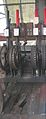 Signal levers, Switzerland
 -
 A traditional UK signal box
 -
 Inside a signal box on the Isle of Wight Steam Railway
 -

-
 Walton Street Crossing Box, Hull, Humberside ,England.
 -
 An active signal cabin at Shaw and Crompton railway station, in Greater Manchester, England.
 -
 A disused signal box at Liverpool Street station
 -
 Chappel South box at The East Anglian Railway Museum


