

In materials science, a metal foam is a material or structure consisting of a solid metal (frequently aluminium) with gas-filled pores comprising a large portion of the volume. The pores can be sealed (closed-cell foam) or interconnected (open-cell foam).[1] The defining characteristic of metal foams is a high porosity: typically only 5–25% of the volume is the base metal. The strength of the material is due to the square–cube law.
Metal foams typically retain some physical properties of their base material. Foam made from non-flammable metal remains non-flammable and can generally be recycled as the base material. Its coefficient of thermal expansion is similar while thermal conductivity is likely reduced.[2]
Definitions[edit]
Open-cell[edit]


Open-celled metal foam, also called metal sponge,[3] can be used in heat exchangers (compact electronics cooling, cryogen tanks, PCM heat exchangers), energy absorption, flow diffusion, CO2 scrubbers, flame arrestors, and lightweight optics.[4] The high cost of the material generally limits its use to advanced technology, aerospace, and manufacturing.
Fine-scale open-cell foams, with cells smaller than can be seen unaided, are used as high-temperature filters in the chemical industry.
Metal foams are used in compact heat exchangers to increase heat transfer at the cost of reduced pressure.[5][6][7][clarification needed] However, their use permits substantial reduction in physical size and fabrication costs. Most models of these materials use idealized and periodic structures or averaged macroscopic properties.
Metal sponge has very large surface area per unit weight and catalysts are often formed into metal sponge, such as palladium black, platinum sponge, and spongy nickel. Metals such as osmium and palladium hydride are metaphorically called "metal sponges", but this term is in reference to their property of binding to hydrogen, rather than the physical structure.[8]
Closed-cell[edit]
Closed-cell metal foam was first reported in 1926 by Meller in a French patent where foaming of light metals, either by inert gas injection or by blowing agent, was suggested.[9] Two patents on sponge-like metal were issued to Benjamin Sosnik in 1948 and 1951 who applied mercury vapor to blow liquid aluminium.[10][11]
Closed-cell metal foams were developed in 1956 by John C. Elliott at Bjorksten Research Laboratories. Although the first prototypes were available in the 1950s, commercial production began in the 1990s by Shinko Wire company in Japan. Closed-cell metal foams are primarily used as an impact-absorbing material, similarly to the polymer foams in a bicycle helmet but for higher impact loads. Unlike many polymer foams, metal foams remain deformed after impact and can therefore only be deformed once. They are light (typically 10–25% of the density of an identical non-porous alloy; commonly those of aluminium) and stiff and are frequently proposed as a lightweight structural material. However, they have not been widely used for this purpose.
Closed-cell foams retain the fire resistance and recycling potential of other metal foams, but add the property of flotation in water.
Stochastic foam[edit]
A foam is said to be stochastic when the porosity distribution is random. Most foams are stochastic because of the method of manufacture:
- Foaming of liquid or solid (powder) metal
- Vapor deposition (CVD on a random matrix )
- Direct or indirect random casting of a mold containing beads or matrix
Regular foam[edit]

A foam is said to be regular when the structure is ordered. Direct molding is one technology that produces regular foams[12][13] with open pores. Metal foams can also be produced by additive processes such as selective laser melting (SLM).
Plates can be used as casting cores. The shape is customized for each application. This manufacturing method allows for "perfect" foam, so-called because it satisfies Plateau's laws and has conducting pores of the shape of a truncated octahedron Kelvin cell (body-centered cubic structure).

Hybrid foam[edit]
Hybrid metal foams typically have a thin film on the underlying porous substrate.[15] Coating metal foams with a different material has been shown to improve the mechanical properties of the metal foam, especially because they are prone to bending deformation mechanisms due to their cellular structure. The addition of a thin film can also improve other properties such as corrosion resistance and enable surface functionalization for catalytic flow processes.
To fabricate hybrid metal foams, thin films are deposited onto a foam substrate with electrodeposition at room temperature.[16] A two-electrode cell setup in a Watt's bath can be used.[16] Recent studies have demonstrated issues with the uniformity of the thin-film due to the complex geometry of metal foams.[16] Issues with uniformity have been addressed in more recent studies through the implementation of nanoparticle thin films, leading to improved mechanical and corrosion resistance properties.[17]
Recent studies on hybrid foams have also been used to address non-renewable energy resources.[18] Transition metal hybrid foams have previously been fabricated through a combination of electrodeposition and hydrogen bubbling processes to enhance the diffusivity of fluids through the porous material and improve the electrical properties for enhanced charge transfer.[18] Thus, such foams can be used to make electrocatalytic water splitting processes more efficient.
Hybrid metal foams may have favorable conductive properties for flexible devices. Through the application of a thin layer of metal onto a porous polymer substrate via gas-phase deposition, researchers have been able to achieve high conductivity while maintaining the flexibility of the polymer matrix.[19] Through cycling testing, it has been shown that hybrid foams are capable of surface deformation sensing.[19] Future efforts seek to characterize the change in cross-linking and porosity of materials as deposition occurs. Additionally, the interaction or compatibility between different polymers and metals in foam ligands can be explored in order to get an improved understanding of their sensitivity to external forces. This would help improve resistance to compressive forces.
Manufacturing[edit]
Open-cell[edit]
Open cell foams are manufactured by foundry or powder metallurgy. In the powder method, "space holders" are used; as their name suggests, they occupy the pore spaces and channels. In casting processes, foam is cast with an open-celled polyurethane foam skeleton.
Closed-cell[edit]
Foams are commonly made by injecting a gas or mixing a foaming agent into molten metal.[20] Molten metal can be foamed by creating gas bubbles in the material. Normally, bubbles in molten metal are highly buoyant in the high-density liquid and rise quickly to the surface. This rise can be slowed by increasing the viscosity of the molten metal by adding ceramic powders or alloying elements to form stabilizing particles in the molten metal, or by other means. Molten metal can be foamed in one of three ways:
- by injecting gas into the liquid metal from an external source;
- by causing gas formation in the liquid by admixing gas-releasing blowing agents with the molten metal;
- by causing the precipitation of gas that was previously dissolved in the molten metal.
To stabilize the molten metal bubbles, high temperature foaming agents (nano- or micrometer- sized solid particles) are required. The size of the pores, or cells, is usually 1 to 8 mm. When foaming or blowing agents are used, they are mixed with the powdered metal before it is melted. This is the so-called "powder route" of foaming, and it is probably the most established (from an industrial standpoint). After metal (e.g. aluminium) powders and foaming agent (e.g. TiH2) have been mixed, they are compressed into a compact, solid precursor, which can be available in the form of a billet, a sheet, or a wire. Production of precursors can be done by a combination of materials forming processes, such as powder pressing,[21] extrusion (direct[22] or conform[23]) and flat rolling.[24]
Composite metal foam[edit]

Composite metal foam is made from a combination of homogeneous hollow metal spheres with a metallic matrix surrounding the spheres. This closed-cell metal foam isolates the pockets of air within and can be made out of nearly any metal, alloy, or combination. The sphere sizes can be varied and fine-tuned per application. The mixture of air-filled hollow metal spheres and a metallic matrix provides both light weight and strength. The spheres are randomly arranged inside the material but most often resembles a simple cubic or body-centered cubic structure. CMF is made out of about 70% air and thus, weighs 70% less than an equal volume of the solid parent material. Composite metal foam is the strongest metal foam available with a 5-6 times greater strength to density ratio and over 7 times greater energy absorption capability than previous metal foams.[25] CMF was developed at North Carolina State University by the inventor Afsaneh Rabiei with four patents in her name, all entitled "Composite Metal Foam and Method of Preparation Thereof" (US Utility Patents 9208912, 8110143, 8105696, 7641984), and CMF is currently proprietary technology owned by the company Advanced Materials Manufacturing.
High-speed impact/blast/ballistics testing[edit]
A plate less than one inch thick has enough resistance to turn a .30-06 Springfield standard-issue M2 armour-piercing bullet to dust. The test plate outperformed a solid metal plate of similar thickness, while weighing far less. Other potential applications include nuclear waste (shielding X-rays, gamma rays and neutron radiation) transfer and thermal insulation for space vehicle atmospheric re-entry, with many times the resistance to fire and heat as the plain metals.[25] Another study testing CMF's resistance to .50 caliber rounds found that CMF could stop such rounds at less than half the weight of rolled homogeneous armour.[26]
HEI/fragment testing[edit]
CMF can replace rolled steel armour with the same protection for one-third the weight. It can block fragments and the shock waves that are responsible for traumatic brain injuries (TBI). CMF was tested against blasts and fragments. The panels were tested against 23 × 152 mm high explosive incendiary rounds (as in anti-aircraft weapons) that release a high-pressure blast wave and metal fragments at speeds up to 1524 m/s. The CMF panels were able to withstand the blast and frag impacts without bowing or cracking. The thicker sample (16.7 mm thick) was able to completely stop various-sized fragments from three separate incendiary ammunition tests. It was shown that CMF is able to locally arrest the fragments and dissipate the energy of the incident blast wave and impede the spread of failure, as opposed to fully solid materials that transfers the energy across the entire plate, damaging the bulk material.[27] In this study, stainless steel CMF blocked blast pressure and fragmentation at 5,000 feet per second from high explosive incendiary (HEI) rounds that detonate at 18 inches away. Steel CMF plates (9.5 mm or 16.75 mm thick) that were placed 18 inches from the strike plate held up against the wave of blast pressure and against the copper and steel fragments created by a 23×152 mm HEI round (as in anti-aircraft weapons) as well as a 2.3mm aluminium strikeplate.[28] The performance of the steel CMF was far better than the same weight aluminium plate against the same type of blast and fragments.[29]
Small arms testing[edit]
Composite metal foam panels, manufactured using 2 mm steel hollow spheres embedded in a stainless steel matrix and processed using a powder metallurgy technique, were used together with boron carbide ceramic and aluminium 7075 or Kevlar back panels to fabricate a new composite armour system. This composite armour was tested against NIJ-Type III and Type IV threats using NIJ 0101.06 ballistic test standard. The highly functional layer-based design allowed the composite metal foam to absorb the ballistic kinetic energy effectively, where the CMF layer accounted for 60–70% of the total energy absorbed by the armour system and allowed the composite armour system to show superior ballistic performance for both Type III and IV threats. The results of this testing program suggests that CMF can be used to reduce the weight and increase the performance of armour for Type III and Type IV threats.[30]

.50 caliber AP testing[edit]
CMF has been tested against larger-caliber armour-piercing rounds.[31] S-S CMF panels were manufactured and paired with a ceramic faceplate and aluminium backplate. The layered hard armours were tested against .50 BMG ball and AP rounds at a range of impact velocities. The mild steel cores of the ball rounds penetrated one of the three samples but revealed the benefits of using multiple tiles over a single ceramic faceplate to limit the spread of damage. The hardened steel core of the AP rounds penetrated deep into the ceramic faceplate, compressing the CMF layer until the projectile was either stopped and embedded within the armour or was able to fully penetrate and exit the backing plate. The experimental results were compared to commercially available armour materials and offer improved performance with reduced weight. The CMF layer is estimated to absorb between 69 and 79% of the bullet's kinetic energy, in their unoptimized testing condition.[31] At impact velocities above 800 m/s, the CMF layer consistently absorbed up to 79% of the impact energy. As the impact velocity increased, so did the effective strength of the CMF layer due to the strain rate sensitivity of the material. The mass efficiency ratio of the armours, when compared to rolled homogeneous armour (RHA), was calculated to be 2.1. The CMF hard armours can effectively stop an incoming round at less than half the weight of the required RHA.[26] The weight savings afforded by using such novel armour can improve the fuel efficiency of military vehicles without sacrificing the protection of the personnel or the equipment inside.
Puncture testing[edit]
Composite metal foam has been tested in a puncture test. Puncture tests were conducted on S-S CMF-CSP with different thicknesses of stainless steel face sheets and CMF core. The bonding of the S-S CMF core and face sheets was done via adhesive bonding and diffusion bonding. Various thicknesses of the CMF core and face sheets created a variety of target areal densities from about 6.7 to about 11.7 kg per each tile of 30 x 30 cm. Targets were impacted using 2.54 and 3.175 cm diameter steel balls fired at velocities ranging from 120 to 470 m per second, resulting in puncture energies from 488 to 14 500 J over a 5.06–7.91 cm2 impact area for the two size sphere balls. None of the panels, even those with the lowest areal densities, showed complete penetration/puncture through their thickness. This was mostly due to the energy absorption capacity of the S-S CMF core in compression, whereas the face sheets strengthen the CMF core to better handle tensile stresses. Sandwich panels with thicker face sheets show less effectiveness, and a thin face sheet seemed to be sufficient to support the S-S CMF core for absorbing such puncture energies. Panels assembled using adhesive bonding showed debonding of the face sheets from the CMF core upon the impact of the projectile while the diffusion bonded panels showed more flexibility at the interface and better accommodated the stresses. Most diffusion bonded panels did not show a debonding of face sheets from the S-S CMF core. This study proved CMF's energy absorption abilities, indicating that CMF can be used to simultaneously increase protections and decrease weight.[32]
Fire/extreme heat testing[edit]

A 12" x 12" x 0.6" thick 316L steel CMF panel with a weight of 3.545 kg was tested in a torch-fire test. In this test, the panel was exposed to over 1204 °C temperatures for 30 minutes. Upon reaching the 30 minutes' time of exposure, the maximum temperature on the unexposed surface of the steel was 400 °C (752 °F) at the center of the plate directly above the jet burner. This temperature was well below the required temperature rise limit of 427 °C; therefore, this sample met the torch fire test requirements. For reference, a solid piece of equal volume steel used for calibration failed this test in about 4 minutes.[33]
It is worth mentioning that the same CMF panel prior to the above-mentioned jet fire testing was subjected to a pool-fire test. In this test, the panel was exposed to 827 °C temperatures for 100 minutes. The panel withstood the extreme temperature for 100 minutes with ease, reaching a maximum backface temperature of 379 °C, far below the 427 °C failure temperature. For reference, the test was calibrated using an equal-sized piece of solid steel that failed the test in approximately 13 minutes.[34] These studies indicate the extraordinary performance of CMF against fire and extreme heat.
Composite metal foam has a very low rate of heat transfer and has proven to isolate an extreme temperature of 1,100 °C (2,000 °F) within only a few inches, leaving the material at room temperature just about two inches away from a region of white-hot material. In addition, the steel CMF managed to retain most of its steel-like strength at this temperature while remaining as lightweight as aluminium, a material that would melt instantly at this extreme temperature.
Other abilities[edit]
Composite metal foam has shown an ability to shield against x-ray and neutron radiation, absorbs/mitigates shocks, sounds, and vibrations, and can withstand over 1,000,000 high load cycles, outperforming traditional solid metals in each case.
Regular foams gallery[edit]
-
 Heat sink with copper foam
 -
 Crash box including Aluminium foam
 -
 Aluminium foam with big porosity
 -
 Aluminium foam with aluminium sheet
 -
 Header - steel metal foam


Applications[edit]
Design[edit]
Metal foam can be used in product or architectural composition.
Design gallery[edit]
-
 machined metal foam
 -
![Design heatsink with regular foam[35]](https://upload.wikimedia.org/wikipedia/commons/thumb/3/3a/Design_heatsink.JPG/120px-Design_heatsink.JPG) Design heatsink with regular foam[35]
Design heatsink with regular foam[35] -
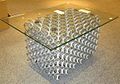 coffee table with large pored aluminium

![Design heatsink with regular foam[35]](https://thcscience.wiki/term/cannabaceae/cannabis/cannabis-ruderalis/?rdp_we_resource=https%3A%2F%2Fen.wikipedia.org%2Fwiki%2FFile%3ADesign_heatsink.JPG)

Mechanical[edit]
Orthopedics[edit]
Foam metal has been used in experimental animal prosthetics. In this application, a hole is drilled into the bone and the metal foam inserted, letting the bone grow into the metal for a permanent junction. For orthopedic applications, tantalum or titanium foams are common for their tensile strength, corrosion resistance and biocompatibility.
The back legs of a Siberian Husky named Triumph received foam metal prostheses. Mammalian studies showed that porous metals, such as titanium foam, may allow vascularization within the porous area.[36]
Orthopedic device manufacturers use foam construction or metal foam coatings[37] to achieve desired levels of osseointegration.[38][39][40]
Automotive[edit]
The primary functions of metallic foams in vehicles are to increase sound damping, reduce weight, increase energy absorption in case of crashes, and (in military applications) to combat the concussive force of IEDs. As an example, foam filled tubes could be used as anti-intrusion bars.[41] Because of their low density (0.4–0.9 g/cm3), aluminium and aluminium alloy foams are under particular consideration. These foams are stiff, fire resistant, nontoxic, recyclable, energy absorbent, less thermally conductive, less magnetically permeable, and more efficiently sound dampening, especially when compared to hollow parts. Metallic foams in hollow car parts decrease weakness points usually associated with car crashes and vibration. These foams are inexpensive to cast with powder metallurgy, compared to casting other hollow parts.
Compared to polymer foams in vehicles, metallic foams are stiffer, stronger, more energy absorbent, and resistant to fire and the weather adversities of UV light, humidity, and temperature variation. However, they are heavier, more expensive, and non-insulating.[42]
Metal foam technology has been applied to automotive exhaust gas.[43] Compared to traditional catalytic converters that use cordierite ceramic as substrate, metal foam substrate offers better heat transfer and exhibits excellent mass-transport properties (high turbulence) and may reduce the quantity of platinum catalyst required.[44]
Electrocatalysis[edit]
Metal foams are popular support for electrocatalysts due to the high surface area and stable structure. The interconnected pores also benefit the mass transport of reactants and products. However, the benchmark of electrocatalysts can be difficult due to the undetermined surface area, different foam properties, and capillary effect.[45]
Energy absorption[edit]

Metal foams are used for stiffening a structure without increasing its mass.[46] For this application, metal foams are generally closed pore and made of aluminium. Foam panels are glued to the aluminium plate to obtain a resistant composite sandwich locally (in the sheet thickness) and rigid along the length depending on the foam's thickness.
The advantage of metal foams is that the reaction is constant, regardless of the direction of the force. Foams have a plateau of stress after deformation that is constant for as much as 80% of the crushing.[47]
Thermal[edit]


Tian et al.[48] listed several criteria to assess a foam in a heat exchanger. The comparison of thermal-performance metal foams with materials conventionally used in the intensification of exchange (fins, coupled surfaces, bead bed) first shows that the pressure losses caused by foams are much more important than with conventional fins, yet are significantly lower than those of beads. The exchange coefficients are close to beds and ball and well above the blades.[49][50]
Foams offer other thermophysical and mechanical features:
- Very low mass (density 5–25% of the bulk solid depending on the manufacturing method)
- Large exchange surface (250–10000 m2/m3)
- Relatively high permeability
- Relatively high effective thermal conductivities (5–30 W/(mK))
- Good resistance to thermal shocks, high pressures, high temperatures, moisture, wear and thermal cycling
- Good absorption of mechanical shock and sound
- Pore size and porosity can be controlled by the manufacturer
Commercialization of foam-based compact heat exchangers, heat sinks and shock absorbers is limited due to the high cost of foam replications. Their long-term resistance to fouling, corrosion and erosion are insufficiently characterized. From a manufacturing standpoint, the transition to foam technology requires new production and assembly techniques and heat exchanger design.
Kisitu et al. [51][52] pioneered the experimental investigation of using compressed copper foam for advanced two-phase cooling for high heat flux electronics. The metallic foam samples are designed and manufactured by a US-based company, ERG Aerospace Corporation.[53] Heat fluxes as high as 174 W/cm2 were tested/handled. Data reveal that compressing the foam by four times in the streamwise direction (4X) enhanced thermal performance by more than 3 times, compared to the uncompressed metal foam. This was attributed to the fact that compressing foam proportionally reduces the effective hydraulic diameter and increases both the surface area per unit volume and foam bulk thermal conductivity, which all improve two-phase cooling performance. In addition, results show that compressed foam has a potential to increase the critical heat flux (CHF), which is pivotal in the safe operation of two-phase cooling at high heat densities. Preliminarly results show that compressed metallic foams can solve several issues faced with microchannels, including clogging, flow instabilities, low CHF, and others. As such, compressed foams are being proposed as new powerful alternatives to microchannels in pumped two-phase cooling for high heat flux electronics cooling/thermal management, including high performance computers, aerospace, military and defence, and power electronics.
See also[edit]
- Aluminium foam sandwich
- Aluminum polymer composite
- Ceramic foam
- Nanofoam
- Porous medium
- Reticulated foam
- Titanium foam
References[edit]
- ^ "Metallic & Ceramic Foams | American Elements | Products | Applications". American Elements. Retrieved 2024-03-21.
- ^ Compare Materials: Cast Aluminium and Aluminium Foam Archived 2010-04-30 at the Wayback Machine. Makeitfrom.com. Retrieved on 2011-11-19.
- ^ John Banhart. "What are cellular metals and metal foams?" Archived 2010-12-29 at the Wayback Machine
- ^ "Duocel® Metal Foam Material". ergaerospace.com/. Retrieved 2022-01-26.
- ^ Topin, F.; Bonnet, J. -P.; Madani, B.; Tadrist, L. (2006). "Experimental Analysis of Multiphase Flow in Metallic foam: Flow Laws, Heat Transfer and Convective Boiling" (PDF). Advanced Engineering Materials. 8 (9): 890. doi:10.1002/adem.200600102. S2CID 138133942.
- ^ Banhart, J. (2001). "Manufacture, Characterization and application of cellular metals and metal foams". Progress in Materials Science. 46 (6): 559–632. doi:10.1016/S0079-6425(00)00002-5.
- ^ DeGroot, C.T.; Straatman, A.G.; Betchen, L.J. (2009). "Modeling forced convection in finned metal foam heat sinks". Journal of Electronic Packaging. 131 (2): 021001. doi:10.1115/1.3103934.
- ^ Ralph Wolf; Khalid Mansour. "The Amazing Metal Sponge: Soaking Up Hydrogen" Archived 2015-11-16 at the Wayback Machine. 1995.
- ^ De Meller, M.A. French Patent 615,147 (1926).
- ^ Sosnick, B. U.S. patent 2,434,775 (1948).
- ^ Sosnick, B. U.S. patent 2,553,016 (1951).
- ^ a b Recherche sur la production de pièces de fonderie en mousse métallique – Recherche en fonderie : les mousses métalliques Archived 2013-10-29 at the Wayback Machine. Ctif.com. Retrieved on 2013-12-03.
- ^ a b ALVEOTEC – Innovation Archived 2014-07-30 at the Wayback Machine. Alveotec.fr/en. Retrieved on 2013-12-03.
- ^ "ALVEOTEC - Actualités - video : making process of aluminium foam". Archived from the original on 2014-07-30.
- ^ Jung, A.; Koblischka, M. R.; Lach, E.; Diebels, S.; Natter, H. (2012). "Hybrid Metal Foams". International Journal of Material Science. 2 (4): 97–107.
- ^ a b c Bouwhuis, B. A.; McCrea, J. L.; Palumbo, G.; Hibbard, G. D. (2009). "Mechanical properties of hybrid nanocrystalline metal foams". Acta Materialia. 57 (14): 4046–4053. Bibcode:2009AcMat..57.4046B. doi:10.1016/j.actamat.2009.04.053.
- ^ Xu, Y.; Ma, S.; Fan, M.; Zheng, H.; Chen, Y.; Song, X.; Hao, X. (2019). "Mechanical and Corrosion Resistance Enhancement of Closed-Cell Aluminum Foams through Nano-Electrodeposited Composite Coatings". Materials. 12 (19): 2197. Bibcode:2019Mate...12.3197X. doi:10.3390/ma12193197. PMC 6803920. PMID 31569520.
- ^ a b Zhou, J.; Yu, L.; Zhou, Z.; Huang, C.; Zhang, Y.; Yu, B.; Yu, Y. (2021). "Ultrafast fabrication of porous transition metal foams for efficient electrocatalytic water splitting". Applied Catalysis B: Environmental. 288: 120002. doi:10.1016/j.apcatb.2021.120002. S2CID 233541520.
- ^ a b Peng, Y.; Liu, H.; Zhang, J. (2020). "Hybrid Metallic Foam with Superior Elasticity, High Electrical Conductivity, and Pressure Sensitivity". ACS Applied Materials and Interfaces. 12 (5): 6489–6495. doi:10.1021/acsami.9b20652. PMID 31927977. S2CID 210191505.
- ^ Banhart, John (2000). "Manufacturing Routes for Metallic Foams". JOM. 52 (12). Minerals, Metals & Materials Society: 22–27. Bibcode:2000JOM....52l..22B. doi:10.1007/s11837-000-0062-8. S2CID 137735453. Archived from the original on 2012-01-01. Retrieved 2012-01-20.
- ^ Bonaccorsi, L.; Proverbio, E. (1 September 2006). "Powder Compaction Effect on Foaming Behavior of Uni-Axial Pressed PM Precursors". Advanced Engineering Materials. 8 (9): 864–869. doi:10.1002/adem.200600082. S2CID 136706142.
- ^ Shiomi, M.; Imagama, S.; Osakada, K.; Matsumoto, R. (2010). "Fabrication of aluminium foams from powder by hot extrusion and foaming". Journal of Materials Processing Technology. 210 (9): 1203–1208. doi:10.1016/j.jmatprotec.2010.03.006.
- ^ Lefebvre, Louis Philippe; Banhart, John; Dunand, David C. (2008). MetFoam 2007 : porous metals and metallic foams : proceedings of the fifth International Conference on Porous Metals and Metallic Foams, September 5–7, 2007, Montreal Canada. Lancaster, Pa.: DEStech Publications Inc. pp. 7–10. ISBN 978-1932078282.
- ^ Strano, M.; Pourhassan, R.; Mussi, V. (2013). "The effect of cold rolling on the foaming efficiency of aluminium precursors". Journal of Manufacturing Processes. 15 (2): 227. doi:10.1016/j.jmapro.2012.12.006.
- ^ a b
"Study Finds Metal Foams Capable of Shielding X-rays, Gamma Rays, Neutron Radiation". NC State, Raleigh, North Carolina. NC State University News. July 17, 2015. Retrieved August 20, 2021.
Research from North Carolina State University shows that lightweight composite metal foams are effective at blocking X-rays, gamma rays and neutron radiation, and are capable of absorbing the energy of high impact collisions.
- ^ a b Shipman, Matt Metal Foam Stops .50 Caliber Rounds as Well as Steel – At Less Than Half the Weight, NC State University News, 05.05.19
- ^ Rabiei, Marx, Portanova, (2018), A study on blast and fragment resistance of composite metal foams through experimental and modeling approaches. Composite Structures 194 (2018) 652-661.
- ^ Wang, Brian (2018-04-24). "Composite metal foams provide armour protection for one third the weight and make super car bumpers | NextBigFuture.com". NextBigFuture.com. Retrieved 2018-05-24.
- ^ Marx, Portanova, Rabiei, A study on blast and fragment resistance of composite metal foams through experimental and modeling approaches. Composite Structures 194 (2018) 652-661.
- ^ Rabiei, Garcia-Avila, Portanova. (2015). Ballistic performance of composite metal foams. Composite Structures (2015) 202-211.
- ^ a b c Rabiei, Marx, Portanova. (2019). Ballistic performance of composite metal foam against large-caliber threats. Composite Structures 224 (2019) 111032.
- ^ Rabiei, Marx, Portanova, Scott, Schwandt. (2020). A study on puncture resistance of composite metal foam core sandwich panels. Advanced Engineering Materials (2020) 2000693.
- ^ a b Rabiei, Lattimer, Bearinger, (2020), Recent advances in the analysis, measurement and properties of composite metal foams.
- ^ Rabiei, Karimpour, Basu, Janssens. (2020). Steel-steel composite metal foam in simulated pool fire testing. International Journal of Thermal Sciences 153 (2020) 106336.
- ^ ALVEOTEC - Actualités - LOUPI Lighing launches his new metal foam heatsink for lighting application_66.html Archived 2014-07-30 at the Wayback Machine. Alveotec.fr. Retrieved on 2013-12-03.
- ^ Osseointegration with Titanium Foam in Rabbit Femur Archived 2016-04-18 at the Wayback Machine, YouTube
- ^ Titanium coatings on Orthopedic Devices Archived 2016-03-13 at the Wayback Machine. Youtube
- ^ Biomet Orthopedics, Regenerex® Porous Titanium Construct Archived 2011-09-28 at the Wayback Machine
- ^ Zimmer Orthopedics, Trabeluar Metal Technology Archived 2011-07-18 at the Wayback Machine
- ^ Zimmer CSTiTM (Cancellous-Structured Titanium TM) Porous Coating Archived 2011-07-18 at the Wayback Machine
- ^ Strano, Matteo (2011). "A New FEM Approach for Simulation of Metal Foam Filled Tubes". Journal of Manufacturing Science and Engineering. 133 (6): 061003. doi:10.1115/1.4005354.
- ^ New Concept for Design of Lightweight Automotive Components Archived 2012-03-24 at the Wayback Machine. (PDF) . Retrieved on 2013-12-03.
- ^ Alantum Innovations in Alloy Foam: Home Archived 2010-02-17 at the Wayback Machine. Alantum.com. Retrieved on 2011-11-19.
- ^ Development of Metal Foam Based Aftertreatment on a Diesel Passenger Car – Virtual Conference Center[permanent dead link]. Vcc-sae.org. Retrieved on 2011-11-19.
- ^ Zheng, Weiran; Liu, Mengjie; Lee, Lawrence Yoon Suk (9 October 2020). "Best Practices in Using Foam-Type Electrodes for Electrocatalytic Performance Benchmark". ACS Energy Letters. 5 (10): 3260–3264. doi:10.1021/acsenergylett.0c01958. hdl:10397/100121.
- ^ Banhart, John; Dunand, David C. (2008). MetFoam 2007: Porous Metals and Metallic Foams : Proceedings of the Fifth International Conference on Porous Metals and Metallic Foams, September 5-7, 2007, Montreal Canada. DEStech Publications, Inc. ISBN 9781932078282.
- ^ ALVEOTEC – Actualités – Examples of metal foam applications. Archived 2014-07-30 at the Wayback Machine Alveotec.fr. Retrieved on 2013-12-03.
- ^ Tian, J.; Kim, T.; Lu, T. J.; Hodson, H. P.; Queheillalt, D. T.; Sypeck, D. J.; Wadley, H. N. G. (2004). "The effects of topology upon fluid-flow and heat-transfer within cellular copper structures" (PDF). International Journal of Heat and Mass Transfer. 47 (14–16): 3171. doi:10.1016/j.ijheatmasstransfer.2004.02.010. Archived (PDF) from the original on 2016-03-03.
- ^ Miscevic, M. (1997). Etude de l'intensification des transferts thermiques par des structures poreuses: Application aux échangeurs compacts et au refroidissement diphasique. IUSTI. Marseille., Université de Provence
- ^ Catillon, S., C. Louis, et al. (2005). Utilisation de mousses métalliques dans un réformeur catalytique du méthanol pour la production de H2. GECAT, La Rochelle.
- ^ Kisitu, Deogratius; et al. (2022). "Experimental Investigation of R134a Flow Boiling in Copper Foam Evaporators for High Heat Flux Electronics Cooling". ASME 2022 International Technical Conference and Exhibition on Packaging and Integration of Electronic and Photonic Microsystems (published 2022-12-07). doi:10.1115/ipack2022-97400. ISBN 978-0-7918-8655-7. S2CID 254435507.
{{cite book}}:|website=ignored (help) - ^ Kisitu, Deogratius; Ortega, Alfonso; Zlatinov, Metodi; Schaffarzick, Denver (2023-05-30). "Two-phase flow in compressed copper foam with R134a for high heat flux thermal management: Effects of foam compression ratio and refrigerant operating conditions on thermohydraulic performance". 2023 22nd IEEE Intersociety Conference on Thermal and Thermomechanical Phenomena in Electronic Systems (ITherm). IEEE. pp. 1–10. doi:10.1109/ITherm55368.2023.10177584. ISBN 979-8-3503-2166-1. S2CID 259859929.
- ^ "ERG Aerospace | Home of Patented Duocel Foam | Metal Foam". ergaerospace.com. Retrieved 2022-12-21.
External links[edit]
- Video : Aluminium regular foam: Crash box test
- Video : How regular foams are made
- NASA Fact sheet FS-2003-09-117-MSFC — Viscous Liquid Foam and Bulk Metallic Glass (Foam)
- How to Make an Aluminium Metal Foam on YouTube
- Fischer, S. F.; Thielen, M.; Weiß, P.; Seidel, R.; Speck, T.; Bührig-Polaczek, A.; Bünck, M. (2013). "Production and properties of a precision-cast bio-inspired composite". Journal of Materials Science. 49: 43–51. doi:10.1007/s10853-013-7878-4. S2CID 136318878.
- Bullet destruction video on YouTube